
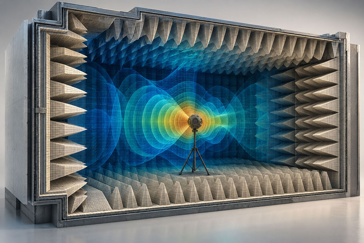
An anechoic chamber is a purpose-built, controlled measurement environment engineered to minimize reflected acoustic energy and reproduce a defined approximation of free-field propagation over a specified frequency range and spatial volume. Achieving this condition requires the coordinated design of the complete facility-not only its absorptive lining, but also its enclosure, structural isolation, ventilation, penetrations, services, access systems, test fixtures, instrumentation supports, measurement geometry, and the device under test. Each of these elements can introduce reflections, background noise, vibration, or transmission paths that influence the integrity and repeatability of the measured result.
Describing an anechoic chamber simply as an “echo-free room” is therefore technically incomplete and can be misleading. No practical chamber is perfectly anechoic at every frequency, position, angle of incidence, and operating condition. Its engineering value is established by qualification: residual reflections, spatial non-uniformity, environmental disturbances, and measurement uncertainty must remain within defined limits for the intended test method, source type, measurement path, and frequency band.
What Is an Anechoic Chamber?
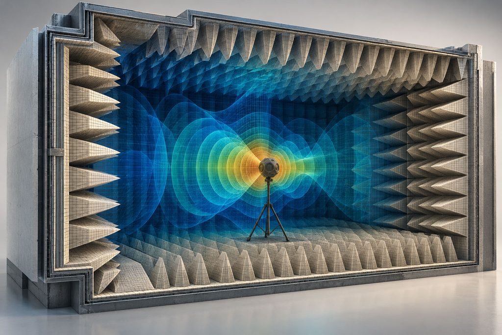
An acoustic anechoic chamber is a specialized room in which the internal boundaries absorb a sufficiently high proportion of incident sound energy for the direct field from the source to dominate within a formally defined measurement region. Within that qualified region, propagation should follow the assumptions of the applicable measurement method closely enough that the chamber’s residual influence can be quantified and included in the overall uncertainty budget.
In an ordinary enclosed room, sound reaches a receiver through many propagation paths. In addition to the direct wave emitted by the source, delayed and directionally altered contributions arrive after reflection from walls, ceiling, floor, doors, windows, equipment, fixtures, and people. These components combine constructively or destructively, producing spatial variations, standing-wave effects, coloration, and level errors that may obscure the true radiation characteristics of the source.
Conceptually, the measured acoustic field contains contributions from the direct sound, reflected sound, and background noise:
p_total = p_direct + Σp_reflected + p_background
The practical objective is therefore not the unattainable elimination of every unwanted contribution, but the systematic reduction and control of those contributions to a level compatible with the required accuracy. A properly specified chamber links this acceptable residual influence to measurable criteria such as allowable deviation from ideal propagation, background-noise margin, spatial uniformity, repeatability, and the dimensions of the qualified test volume.
What Is the Purpose of an Anechoic Chamber?
The primary purpose of an anechoic chamber is to separate the acoustic behavior of a source or device under test from the influence of the surrounding environment. By controlling reflections, external noise, vibration, and service-related disturbances, the chamber enables engineers to measure source level, spectral content, directivity, temporal behavior, and radiation mechanisms under repeatable conditions. This controlled environment supports product development, compliance testing, troubleshooting, model validation, and comparative evaluation across design iterations.
Typical applications span industrial, research, transportation, aerospace, consumer-product, and electro-acoustic programs, including:
- Characterization of sound sources, including spectral content, operating-state dependence, and acoustic signatures
- Precision and engineering-grade sound-power investigations
- Directional radiation measurements and polar-pattern mapping
- Loudspeaker, transducer, and electro-acoustic system testing
- Microphone, sensor, and array characterization or calibration support
- Product-noise development, benchmarking, and design optimization
- Mechanical and electromechanical noise-source identification and diagnostics
- Research into acoustic radiation, propagation, and source mechanisms
- Experimental validation and correlation of numerical acoustic models
- Integrated vibro-acoustic research and development, including structure-borne and airborne pathways
Anechoic, Sound-Isolated, and Reverberant Rooms Are Different
Anechoic, sound-isolated, and reverberant rooms are sometimes treated as interchangeable because each is a specialized acoustic facility. In reality, they are designed to control different physical phenomena and are qualified using different performance indicators. Understanding this distinction is essential when translating a test objective into room requirements.
| Environment | Primary Objective | Dominant Physical Issue |
|---|---|---|
| Anechoic chamber | Suppress internal reflections | Absorption and field quality |
| Sound-isolated room | Limit transmission into or out of the room | Transmission, leakage, and flanking paths |
| Reverberation room | Maintain a controlled reflected acoustic field | Reflection, diffusion, and reverberation |
An anechoic chamber often requires substantial sound isolation, but isolation alone does not create an anechoic environment. A heavily constructed room may achieve very low background noise while still exhibiting strong internal reflections and modal behavior. Conversely, a reverberation room intentionally preserves and diffuses reflected acoustic energy to create a controlled, statistically distributed field. Facility selection must therefore follow the measurement principle: reflection suppression, transmission control, or reverberant-field generation.
The Physics That Determines Anechoic Performance
Free-Field Behavior
In an ideal acoustic free field, sound propagates outward from the source without significant interaction with surrounding boundaries. The pressure and intensity distributions are then governed predominantly by source characteristics, propagation distance, directivity, atmospheric conditions, and geometric spreading rather than by room reflections.
For a compact source radiating approximately spherically, and at distances where the required far-field assumptions are valid, sound pressure level decreases by approximately 6 dB for each doubling of distance from the acoustic center. Chamber reflections disturb this ideal divergence by adding phase-dependent components, creating local increases or decreases in measured level. Qualification measurements therefore examine deviations from the expected distance law along defined traverses and over the frequency range relevant to the intended use.
Acoustic Wavelength and Low-Frequency Performance
Low-frequency performance is one of the defining constraints in anechoic-chamber engineering because acoustic wavelength increases inversely with frequency. The fundamental relationship is:
λ = c / f
where λ is wavelength, c is the local speed of sound, and f is frequency. At 100 Hz, using a representative indoor sound speed of approximately 343 m/s, the wavelength is about 3.43 m. Because sound speed varies with temperature and, to a lesser extent, humidity and composition, environmental conditions should be documented when high-accuracy propagation or calibration work is performed.
As wavelength becomes large relative to absorber depth, clear chamber dimensions, and source-to-boundary distance, effective suppression of reflected energy becomes progressively more demanding. The absorber may no longer provide a sufficiently gradual impedance transition, while room-scale modal behavior and geometric limitations become more influential. These effects increase the required absorber depth, reduce usable test volume, and make it more difficult to maintain compliant free-field behavior throughout the specified measurement region.
Accordingly, the lower operating frequency must never be treated as an isolated marketing figure. A statement such as “the chamber operates down to 100 Hz” is technically meaningful only when tied to a named qualification method, allowable deviation, source and microphone arrangement, traverse geometry, measurement volume, environmental state, and intended application. The current international framework for free-field qualification is ISO 26101-1:2021, which includes discrete-frequency and broadband methods, source requirements, reporting provisions, and measurement uncertainty.
How Anechoic Absorbers Work
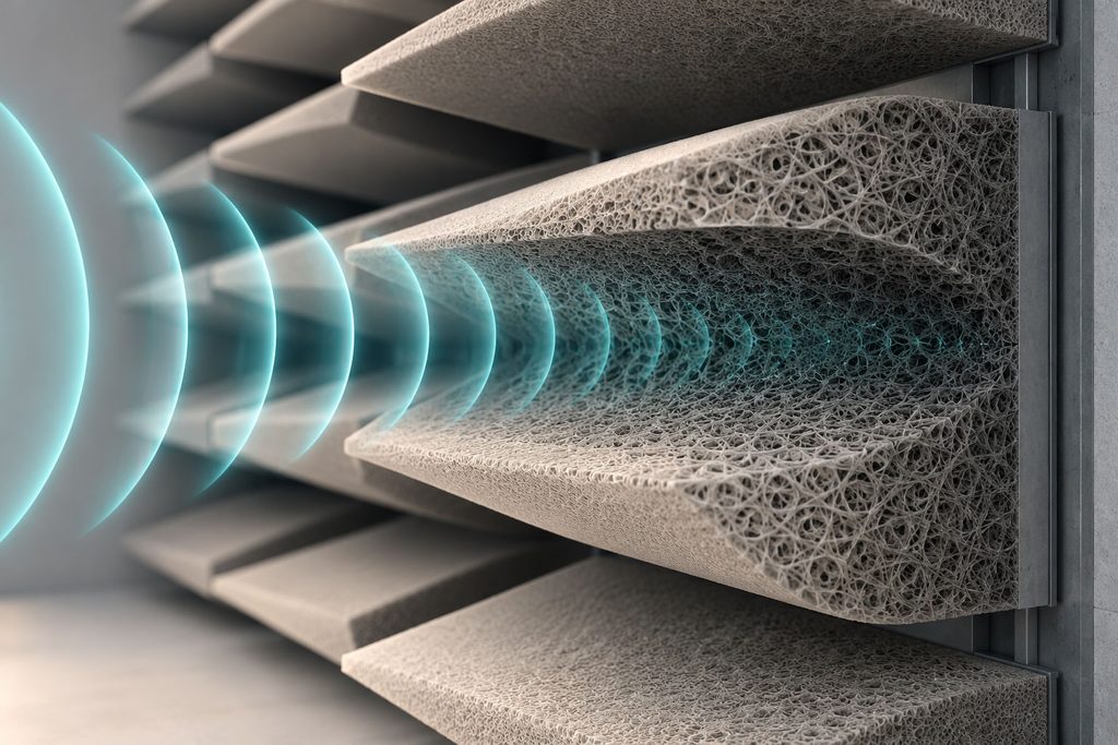
The wedges used in many acoustic anechoic chambers are engineered acoustic devices rather than decorative architectural features. Their geometry, material composition, mounting, protection, orientation, and depth are selected to reduce the acoustic impedance discontinuity between the test volume and the absorbing boundary, thereby limiting the energy reflected back toward the measurement region.
Porous absorbers dissipate acoustic energy through viscous friction and thermal exchange as oscillating air moves through their interconnected pore structure. A tapered wedge increases the effective interaction path and introduces the material progressively, reducing abrupt reflection at the absorber face. At higher frequencies, energy is readily dissipated near the surface and along the taper; at lower frequencies, meaningful attenuation requires greater depth and carefully controlled material properties, including flow resistivity, porosity, density, and structural stability.
Absorber performance depends on several interacting parameters, including:
- Absorber depth
- Material properties and internal structure
- Absorber geometry
- Frequency
- Angle of incidence
- Backing and installation conditions
Increasing absorber depth generally extends useful performance toward lower frequencies, but the design trade-off is substantial. Deeper treatment reduces the clear internal envelope and qualified test volume, increases structural loading and installation complexity, affects lighting and service integration, and may complicate maintenance, fire protection, access, and emergency egress. The optimum solution must therefore balance acoustic performance against available building volume, operational requirements, lifecycle cost, safety, and maintainability.
Full Anechoic vs. Hemi-Anechoic Chambers
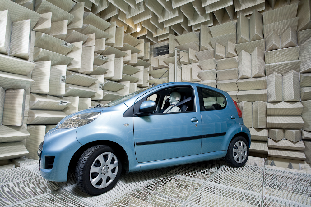
A full anechoic chamber applies absorptive treatment to all six principal boundaries-four walls, ceiling, and floor-to approximate free-field propagation around the test object in three dimensions. This arrangement is particularly valuable when reflections from a supporting plane would conflict with the intended propagation model or when measurements must be made below, above, and around the source.
Because the floor is absorptive, personnel, the test object, and instrumentation normally require a tensioned mesh, cable-supported platform, narrow-frame structure, or another acoustically transparent support system. These supports must satisfy structural and safety requirements while minimizing scattering, vibration transmission, blockage, and changes to the source boundary condition.
A hemi-anechoic chamber retains a hard, reflective floor while treating the walls and ceiling. The floor intentionally represents an acoustically rigid plane, making the configuration appropriate for machinery, vehicles, appliances, and other products that normally operate on or above a hard surface. It also provides practical load-bearing access for heavy equipment, turntables, measurement frames, and service connections.
Neither configuration is inherently superior. The correct choice is determined by the physical boundary condition represented in the relevant test standard or engineering objective, the mass and geometry of the test object, required microphone locations, operational access, and the acceptable influence of the support plane on the measured field.
The Qualified Measurement Volume
One of the most important chamber specifications is not its architectural footprint or gross internal volume, but the three-dimensional region in which the required acoustic conditions have been demonstrated: the qualified measurement volume. This region defines where source positions, microphone locations, arrays, and measurement traverses may be placed while maintaining the stated performance criteria.
The qualified volume can be substantially smaller than the physical room. Absorbers consume clear space; the device under test requires boundary clearance; microphones may need prescribed source distances and angular trajectories; and fixtures, turntables, personnel platforms, robotic positioners, cabling, and safety zones occupy additional volume. Door recesses, lighting, ventilation openings, and local geometric discontinuities may further restrict usable positions.
A chamber may therefore be large enough to contain a machine yet still be unsuitable for the intended measurement. Feasibility must be checked using the complete source envelope, measurement surface, required source-to-microphone distance, positioning tolerances, support arrangement, access path, and distance from absorber tips-not merely the nominal room dimensions.
Near Field, Far Field, and Measurement Geometry
Close to a source, the acoustic field may include reactive and geometric near-field components, strong spatial gradients, and behavior that depends sensitively on source dimensions and phase distribution. At greater distances, the field may approach the far-field conditions assumed by a particular method, but the required distance is source- and frequency-dependent. Measurement geometry must therefore be established from the source size, operating wavelength, directivity, applicable standard, and available qualified volume; a chamber cannot compensate for an invalid source–receiver arrangement.
The Anechoic Chamber Challenge: Controlling the Complete System
In practice, chamber performance depends on the interaction of acoustic, structural, mechanical, architectural, and measurement systems. Potential interference paths include:
- Airborne transmission through the enclosure, doors, seals, and penetrations
- Structural vibration transmitted through the building, supports, or services
- Ventilation and duct-borne noise
- Electrical, mechanical, piping, and cable interfaces
- Test-object supports and measurement fixtures
- Nearby building services, machinery, transportation, or industrial activity
The practical performance of the facility can be limited by any one of these paths. Effective internal absorption cannot compensate for a noisy ventilation opening, a structural vibration bridge, an uncontrolled penetration, or a test fixture that significantly disturbs the acoustic field.
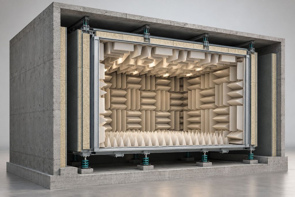
Structural Vibration
Pumps, fans, HVAC equipment, adjacent laboratories, transportation, and industrial machinery can transmit vibration into the chamber structure.
This vibration can excite chamber surfaces, test fixtures, instrumentation supports, or the device under test, introducing signals unrelated to the phenomenon being investigated.
Structural isolation should therefore be approached as a load-path problem. The analysis must consider not only the primary structural connections, but also secondary transmission paths through ducts, pipes, cables, and other services.
Background Noise
Background-noise performance is normally specified as an A-weighted level, a one-third-octave band spectrum, or a limiting NR/NC curve, evaluated with the chamber’s mechanical services in their intended operating state. The lowest technically achievable level is not necessarily the appropriate design target.
The requirement should instead be derived from the expected measurement signal and the uncertainty that can be tolerated. A useful design sequence is:
Expected signal → allowable measurement uncertainty → required signal-to-background relationship → background-noise requirement
Ventilation and Thermal Control
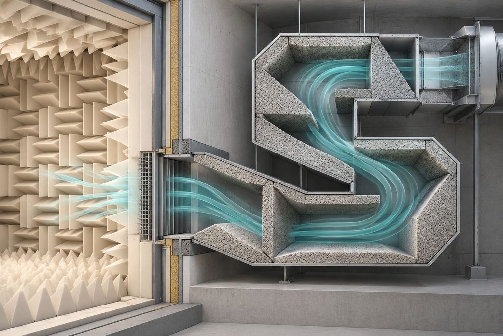
Ventilation is one of the more difficult interfaces in low-noise chamber design.
People and operating equipment generate heat, and many R&D tests require controlled environmental conditions. At the same time, mechanical services can introduce fan noise, airflow-generated noise, duct-borne sound, structural vibration, cross-talk, and acoustic leakage.
Anechoic Chamber Simulation
Simulation can reduce uncertainty in anechoic chamber design, but there is no single numerical model appropriate for every problem. The modeling approach should be selected according to the physical mechanism and design question being investigated.
Depending on the problem, simulation may address acoustic fields and residual reflections, low-frequency behavior, structural modes and vibration transmission, structural-acoustic coupling, test-support dynamics, ventilation, thermal behavior, or interactions between these phenomena.
Anechoic Chamber Qualification and Measurement Uncertainty
Construction completion does not establish chamber performance. The completed facility must be evaluated against measurable requirements derived from its intended use.
Depending on the application, qualification may address:
- Background noise
- Free-field behavior and frequency-dependent deviations
- Spatial variation and qualified measurement volume
- External sound isolation
- Structural vibration
- Mechanical-service operating conditions
- Measurement repeatability
Free-field qualification examines whether measured propagation remains within specified deviations from ideal geometric divergence over defined frequencies, source positions, microphone traverses, and spatial regions. The current international method is ISO 26101-1:2021, which addresses qualification of free-field environments using discrete-frequency and broadband procedures and requires appropriate reporting of measurement uncertainty. For precision sound-power and sound-energy determination in anechoic and hemi-anechoic rooms, ISO 3745:2012 remains current and was confirmed in 2026; it defines requirements for the test room, instrumentation, source installation and operation, measurement surfaces, background-noise correction, and uncertainty. Project specifications should cite the applicable edition and amendment explicitly rather than referring generically to “ISO qualification.”
Acoustic Anechoic Chamber vs. RF Anechoic Chamber
The term “anechoic chamber” is used in both acoustics and radio-frequency engineering because both disciplines seek to suppress unwanted reflected wave energy and create a controlled test environment. The similarity is conceptual, however: acoustic pressure waves and electromagnetic waves obey different material interactions, boundary conditions, scaling relationships, safety requirements, instrumentation practices, and qualification methods.
Acoustic chambers use porous, fibrous, membrane, or resonant treatments to control sound reflections and frequently require stringent management of airborne transmission, background noise, structural vibration, and ventilation noise. RF chambers use electromagnetic absorbers-often pyramidal or hybrid materials-together with conductive shielding, filtered services, bonded penetrations, and field-specific antenna geometries. A facility designed for one discipline should not be assumed suitable for the other without a dedicated technical assessment.
The Anechoic Chamber at Dynamica
Dynamica’s acoustic laboratories include both a full anechoic chamber and a hemi-anechoic room. The full anechoic chamber was manufactured by Eckel Industries and has an internal volume of approximately 100 m³, with all six boundaries – walls, ceiling, and floor – lined with anechoic wedges, and is specified to a lower cut-off frequency of 150 Hz. The measured background-noise level inside the chamber is 17 dB(A), which permits low-level sources to be characterized with an adequate margin above the ambient. The cut-off frequency defines the frequency range over which free-field conditions can be relied upon for quantitative measurement; below it, residual reflections become significant and results must be interpreted accordingly.
Because the floor is absorptive, test objects and instrumentation are supported on structures designed to interfere as little as practical with the acoustic field. The facility is used for sound-power and directivity measurements, loudspeaker and component characterization, product noise development, and experimental validation of numerical models. The hemi-anechoic room retains a reflective floor, which suits measurements intended to represent a source operating above a hard plane and provides practical support for heavier equipment. Together with Dynamica’s reverberation room, the two configurations allow the boundary conditions of the test to be matched to the measurement objective.
Frequently Asked Questions About Anechoic Chambers
What is an anechoic chamber?
An anechoic chamber is a controlled acoustic measurement facility designed to suppress reflected sound energy and reproduce a specified approximation of free-field conditions within a defined frequency range and measurement region. Its performance is established through qualification measurements, not by appearance alone, and must account for residual reflections, background noise, vibration, source geometry, measurement position, and uncertainty.
Is an anechoic chamber completely silent?
No. “Anechoic” refers primarily to control of reflections, whereas “silent” refers to the absence of audible or measurable sound. A chamber may provide excellent free-field behavior yet still contain residual noise from ventilation, electrical equipment, building services, external activity, or structural vibration. Conversely, a very quiet room may remain highly reflective. Chamber suitability must therefore be assessed using both field-quality and background-noise criteria.
Is an anechoic chamber soundproof?
Not necessarily. Sound isolation limits acoustic transmission into or out of a room through walls, doors, seals, penetrations, ducts, and flanking paths. Anechoic treatment controls reflections generated inside the room. High-quality measurement facilities commonly require both functions, but they are achieved by different construction principles and verified by different tests.
Why are anechoic chambers covered with wedges?
Deep wedges and related porous absorbers provide a gradual transition from the air-filled test zone into the absorbing material, reducing the abrupt impedance change that would otherwise produce reflection. The taper also increases the interaction path through the porous medium, where viscous and thermal losses convert acoustic energy into very small amounts of heat. Performance depends on depth, geometry, flow resistivity, porosity, density, protective facing, angle of incidence, backing, installation quality, and frequency.
What determines the lower frequency limit of an anechoic chamber?
The lower useful frequency is determined by the performance of the complete facility rather than by absorber depth alone. Relevant factors include absorber material and geometry, chamber dimensions, boundary discontinuities, source characteristics, source and microphone positions, required qualified volume, background noise, and the allowable deviation specified by the governing test method. The cut-off frequency should therefore be stated together with the qualification criterion and test configuration.
What is the difference between full and hemi-anechoic chambers?
A full anechoic chamber treats the walls, ceiling, and floor so that sound can propagate with minimal reflection around the source. A hemi-anechoic chamber retains a hard reflective floor while treating the remaining principal boundaries, representing a source operating above an acoustically rigid plane. The correct option depends on the applicable standard, the real operating boundary condition, test-object mass, access needs, support arrangement, and required microphone geometry.
Can an anechoic chamber be simulated before construction?
Yes. Numerical analysis can be used before construction to investigate low-frequency acoustic behavior, residual reflections, absorber concepts, structural modes, vibration-transmission paths, support dynamics, ventilation noise, airflow, thermal loads, and coupled multiphysics effects. The model must be selected for the relevant mechanism and supported by defensible material, source, damping, and boundary-condition data. Simulation reduces design risk, but it does not replace commissioning and experimental qualification of the completed facility.
How is an anechoic chamber qualified?
Qualification verifies that the completed chamber provides the specified acoustic environment over the required frequencies, source positions, microphone paths, and spatial region. Under ISO 26101-1:2021, free-field performance may be evaluated using discrete-frequency or broadband methods and reported with the associated uncertainty. Depending on intended use, the commissioning program may also verify background-noise spectra, sound isolation, structural vibration, ventilation operating modes, environmental stability, repeatability, and the influence of fixtures or support systems.
Conclusion
An anechoic chamber is best understood as an integrated precision-measurement system rather than simply a quiet room lined with absorbers. Its value arises from the controlled interaction of acoustic treatment, enclosure isolation, structural dynamics, ventilation, services, test supports, instrumentation, operating procedures, and formal qualification.
The facility is successful only when it delivers the required acoustic field, background-noise margin, usable measurement volume, repeatability, and uncertainty under the operating conditions relevant to the experiment. Sound engineering practice therefore begins with the measurement objective, converts that objective into traceable performance requirements, coordinates all architectural and building-service interfaces, validates critical assumptions through analysis and simulation, and confirms the completed chamber through documented commissioning and qualification.